How to reduce energy loss in solar mounting systems is becoming a practical priority for China’s rapidly expanding photovoltaic market. Mounting structures do more than hold panels. Their design affects shading, tilt accuracy, airflow, cable routing, corrosion resistance, and long-term alignment.
Industry evidence shows why small details matter. The International Energy Agency Photovoltaic Power Systems Programme identifies soiling, shading, mismatch, temperature, and system downtime as major contributors to PV performance losses. NREL’s photovoltaic operations and maintenance research also stresses inspection, preventive maintenance, and reliable fault detection. Fraunhofer ISE’s Photovoltaics Report highlights the continuing importance of system design, module temperature, and installation quality in real-world energy yield.
John Wohlgemuth, a longtime NREL photovoltaic reliability expert, stated, “The goal is to have a 25-year life for PV modules.” That principle should also guide mounting-system decisions. A loose clamp, uneven rail, or poorly planned row spacing can create losses that remain invisible until production data declines. The problem is rarely dramatic.
It is usually cumulative.
For Chinese solar projects, reducing these losses requires more than selecting low-cost steel. Engineers should verify structural tolerances, optimize row spacing with site-specific shading analysis, maintain rear-panel ventilation, and use corrosion-resistant fasteners. Torque records and thermal inspections add useful evidence after installation. Still, no mounting system eliminates every loss. Weather, dust, construction errors, and aging remain uncertain. This article examines measurable methods for reducing those risks, while acknowledging that design assumptions should always be tested against operating data.
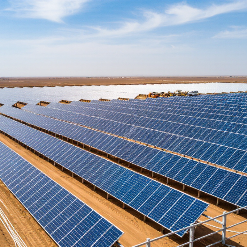
Solar mounting systems in China support rooftops, factories, farms, and large ground projects. Their structure usually includes foundations, posts, beams, rails, clamps, fasteners, and grounding parts. Fixed-tilt systems remain common, while trackers serve selected utility-scale sites. Aluminum rails resist corrosion, and galvanized steel provides structural strength. Stainless-steel fasteners help reduce rust at exposed joints.
Design affects energy production more than many buyers expect. Correct tilt and azimuth improve sunlight capture. Proper row spacing limits inter-row shading. Stable foundations also prevent module movement during strong wind. The IEA PVPS Trends 2024 report recorded more than 440 GW of new solar capacity worldwide in 2023. At this scale, small mounting errors can create significant losses. NREL research has reported typical annual soiling losses near 2% in many locations, with dusty areas performing worse. Therefore, drainage, cleaning access, and module clearance deserve early attention.
Tips: Check structural drawings against the real roof or soil conditions. Measure shadows during different seasons. Avoid overtightening clamps, which can stress module frames. Use compatible metals to reduce galvanic corrosion. The overlooked detail is often cable routing. Loose cables may rub against rails, collect water, or create maintenance risks. In practice, no design is perfect. A lower-cost structure can still work, but only after wind, corrosion, shading, and installation tolerances are reviewed honestly.
A solar mounting system does more than hold panels in place. Its geometry can quietly increase or reduce energy loss. Poor spacing may create row-to-row shading, especially during winter mornings and late afternoons. A careful layout considers roof direction, panel height, seasonal sun angles, and nearby obstructions.
Panels operating above their rated temperature usually produce less electricity. A small air gap beneath the modules allows heat to escape through natural airflow. However, a larger gap is not always better. It can increase wind pressure and structural demands. Engineers should verify wind and snow loads under local building codes.
Uneven mounting surfaces can twist frames and create stress across modules. This may lead to poor electrical performance over time. Accurate measurements are essential. Field inspections should check roof slopes, fastener positions, drainage paths, and cable routes. Cables pressed against metal edges can suffer damage, while loose cables may collect water and dirt.
Reflective roofs can also influence light reaching the rear of bifacial panels, but only when the mounting height and surface condition support it. Dust, bird deposits, and standing water may reduce that benefit. A design drawing can look efficient yet perform differently on site. This is where monitoring data and periodic inspections become valuable. No mounting plan is perfect, and local weather, roof aging, and installation errors deserve honest review.
China Best Solar Mounting Systems: How to Reduce Energy Loss?
Selecting the best mounting system starts with local climate and site conditions. In coastal areas, salty air can accelerate corrosion, so protective coatings and suitable metals matter. Inland sites may face dust, strong temperature changes, or heavy winds. Snow regions need careful load calculations and stronger roof connections. A mounting system that works well in one province may perform poorly elsewhere.
Site surveys should check roof age, slope, drainage, shading, and structural strength. Uneven surfaces can create unstable panel angles and small production losses. Wind exposure also affects rail spacing and fastener selection. Thermal expansion deserves attention, especially on large rooftop arrays. Field inspections often reveal simple problems, such as blocked drainage or loose cables. These details are easy to miss. They still matter.
Tips: Ask a qualified local engineer to review wind and snow data. Use corrosion-resistant materials near the coast. Keep panels clear of vents and shadows. Leave space for inspection and cleaning. Do not choose the cheapest structure automatically; replacement work can cost more. A perfect design is rare. Recheck assumptions before installation, because drawings may not reflect actual roof conditions. Regular inspections can identify movement, rust, and drainage issues before they increase energy loss.
Selecting the Best Mounting System for Local Climate and Site Conditions
The chart shows the estimated module power loss caused by operating temperatures above the standard test condition of 25°C. The calculation uses a typical crystalline-silicon module temperature coefficient of −0.40% per °C. Open-rack systems with rear ventilation can reduce heat accumulation, while roof-mounted systems require sufficient clearance and airflow, especially in hot climates.
Effective solar panel installation begins before any mounting hardware reaches the roof. An installer should inspect roof condition, structural capacity, orientation, and seasonal shading. Roof load matters.
Panels need consistent spacing and a clear path toward the sun. Even a narrow chimney shadow can reduce output across several modules. Use measured layouts rather than visual guesses. Small details matter.
Mounting rails should remain level, and all fasteners need the specified torque. Over-tightening can deform frames or damage roof materials. Under-tightening is equally risky. That balance is easy to overlook. Cables should follow planned routes without sharp bends or contact with metal edges. Loose cables can collect water, dirt, and heat. Keep connectors elevated and protected from standing water.
Leave enough airflow beneath each panel. Hot panels usually produce less electricity, especially during calm summer afternoons. After installation, check alignment, fastener torque, cable security, and drainage points. Record these checks for future maintenance. An honest inspection may reveal small imperfections, such as uneven rail height or a cable resting too close to the roof. Installers sometimes rush this stage, but careful correction can prevent energy loss for years. Local building and electrical requirements should guide every decision, even when a faster method appears acceptable.
Installation Practices That Improve Solar Panel Efficiency
| Installation Practice | Recommended Technical Target | Energy-Loss Mechanism | Typical Impact When Poorly Installed | Verification Method |
|---|---|---|---|---|
| Optimize panel orientation | Face the array toward the equator; use a tilt close to the site's annual optimum unless seasonal production is the priority. | A non-optimal angle reduces the solar irradiance received by the module surface. | Annual yield can decline by several percentage points when orientation or tilt is materially different from the design target. | Confirm azimuth and tilt with a digital inclinometer, site survey, and production simulation. |
| Eliminate shading | Keep the module surface free from shade during the project's critical solar-production hours; check nearby trees, parapets, equipment, and adjacent rows. | Partial shade can activate bypass diodes and reduce the output of an entire cell substring. | Small areas of shade may cause disproportionate string-level losses, especially in series-connected arrays. | Use a solar path analysis, shade study, and on-site inspection at different times of day. |
| Maintain adequate row spacing | Size inter-row spacing for the site's latitude, tilt, module height, and required winter shading limit. | Rows that are too close shade the lower sections of the following row. | Winter and early-morning or late-afternoon production may be reduced; the exact loss depends on geometry and operating hours. | Check the design with a 3D layout or solar-shading calculation for representative dates. |
| Control module operating temperature | Provide the manufacturer-required rear clearance and avoid blocking natural airflow beneath the modules. | Crystalline-silicon module voltage and power generally decrease as cell temperature rises. | Many modules have a power temperature coefficient near −0.3% to −0.4% per °C above the rated test temperature; the exact value is module-specific. | Review mounting clearance and compare temperature-adjusted IV or performance data. |
| Minimize DC cable voltage drop | Select conductor size and routing to keep the calculated voltage drop within the applicable electrical-code and project-design limit; a common design objective is about 1%–2% on the DC circuit. | Cable resistance converts part of the generated electrical energy into heat. | Long runs, undersized conductors, and high current can create avoidable resistive losses. | Calculate resistance using conductor length, cross-sectional area, material, and operating temperature; confirm with voltage measurements. |
| Use compatible connectors and secure terminations | Use connectors of the same approved type and electrical rating; fully engage, lock, and protect all connections from moisture and mechanical stress. | Loose, incompatible, or contaminated connectors increase contact resistance and can create hot spots. | Localized heating may cause intermittent faults, power loss, insulation damage, or a serious fire risk. | Perform visual inspection, polarity testing, insulation testing, and infrared thermography under load. |
| Reduce mismatch between modules | Group modules with similar electrical characteristics and keep modules with different orientations or shading conditions on separate electrical inputs where possible. | In a series string, current is limited by the lowest-performing module or substring. | Variation in current, orientation, soiling, or shade can reduce string output beyond the loss of the affected module alone. | Review module flash data, string design, operating current, and inverter MPPT behavior. |
| Keep the array clean and drainable | Use a mounting angle and rail layout that prevent standing water and allow safe access for cleaning; establish a site-specific cleaning schedule. | Dust, pollen, bird droppings, and industrial deposits reduce light transmission to the cells. | Soiling losses vary widely by climate and site; regular deposits can reduce output by several percentage points or more. | Compare irradiance-normalized output before and after cleaning and inspect the module surface. |
| Install a structurally stable mounting system | Design for local wind, snow, seismic, corrosion, roof, and foundation conditions in accordance with applicable codes and engineering requirements. | Movement, excessive deflection, or corrosion can alter module alignment, damage frames, or loosen electrical connections. | Misalignment and unplanned downtime can reduce energy yield and shorten system service life. | Check torque, fastener condition, rail alignment, corrosion, foundation integrity, and structural calculations. |
| Separate different orientations and tilts | Connect modules with different azimuths or tilt angles to separate MPPT inputs when the inverter design permits. | Modules with different irradiance profiles do not reach the same maximum-power point at the same time. | Combining dissimilar orientations on one MPPT can reduce maximum-power-point tracking efficiency. | Compare string voltage and current profiles and confirm MPPT grouping against the electrical layout. |
Note: Actual energy losses depend on location, system design, module characteristics, weather, shading, soiling, cable length, and maintenance. Final targets should be confirmed through a site-specific engineering assessment and applicable electrical and structural codes.
High-performing solar mounting systems depend on more than strong materials and accurate installation. Regular maintenance protects alignment, drainage, and electrical performance over many years. In coastal areas of China, salt air can accelerate corrosion around bolts and rail connections. Humid southern regions may also encourage moss near drainage points.
During field inspections, technicians should check clamp torque, rail movement, grounding continuity, and foundation cracks. Loose hardware can change panel angles during strong winds. Even a small alignment error can reduce sunlight capture across an entire row. Clean drainage paths matter too. Standing water quietly damages metal surfaces.
Monitoring equipment should record power output, inverter alerts, temperature, and unusual differences between array sections. A sudden drop may indicate shading, cable damage, or structural movement. Compare daily data with weather conditions before scheduling repairs. This avoids replacing healthy components by mistake. Use calibrated tools and keep dated inspection records. Records matter.
Maintenance plans should include checks after heavy rain, typhoons, snow, or construction nearby. No plan is perfect. Dust levels, access problems, and delayed inspections can still create energy losses. A practical team reviews missed tasks each quarter and adjusts inspection frequency. Small corrections are usually safer and less expensive than waiting for visible failure.
Coastal salt can accelerate corrosion, while inland dust, temperature changes, and strong winds create different challenges.
Check roof age, slope, drainage, shading, orientation, and structural strength. Roof load matters.
Snow regions need careful load calculations and stronger roof connections. Wind exposure influences rail spacing and fastener selection.
Yes. Uneven rails can create unstable panel angles and small production losses. Small errors accumulate.
Use measured layouts and keep panels away from chimneys, vents, and seasonal shadows. A narrow shadow can affect several modules.
Airflow helps limit heat buildup. Hot panels usually produce less electricity during calm summer afternoons.
Route cables without sharp bends or metal contact. Keep connectors elevated and away from standing water, dirt, and heat.
Inspect alignment, fastener torque, cable security, drainage, and rail height. Record the results for future maintenance.
Not always. Replacement work may cost more. A low price can hide weak materials or poor site suitability.
Schedule inspections for movement, rust, blocked drainage, and loose cables. Recheck assumptions because drawings may miss real roof conditions.
China’s solar mounting systems combine structural frames, rails, clamps, foundations, fasteners, and tracking components to support panels safely and efficiently. Their design directly affects energy performance: incorrect tilt angles, uneven alignment, shading from structural parts, excessive vibration, and poor cable routing can increase electrical and thermal losses. How to reduce energy loss in solar mounting systems depends on matching the mounting solution to local weather, terrain, roof type, wind pressure, snow load, humidity, and temperature changes. Fixed, adjustable, and tracking systems each offer different benefits and should be selected according to site conditions, project scale, and maintenance capacity.
High-quality installation is equally important. Accurate orientation, secure fastening, suitable spacing, corrosion-resistant materials, and proper drainage help panels operate consistently. Regular inspections should check loose connections, rust, foundation movement, shading growth, and cable damage. Combining performance monitoring with timely cleaning, tightening, repairs, and data analysis can maintain stable output and extend the system’s service life.

Stuart Solar